I made a quick drawing of the system components. It doesn’t include everything but hopefully gives a better overview of the hardware components.
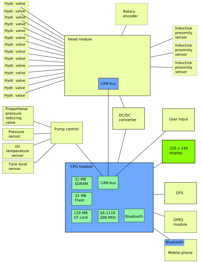
I made a quick drawing of the system components. It doesn’t include everything but hopefully gives a better overview of the hardware components.
Here are some preliminary graphs produced from data logs taken from accelerating a tree in the harvester head. Pump RPM and as a result amount of oil flow are unknown.
First graph shows speed as a function of time:
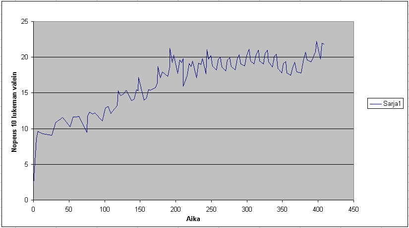
Forward feed has 3 valves in parallel and at the time of taking this capture the second valve was switched on around the 100 ms mark and third valve around 200 ms mark. The speed does seem to begin increasing after opening the second valve but after opening the third valve there isn’t clear indication of speed increase anymore. It’s possible that the oil flow was low enough that two valves were able to pass all the oil flow generated by the pump.
Second graph is speed as a function of position:
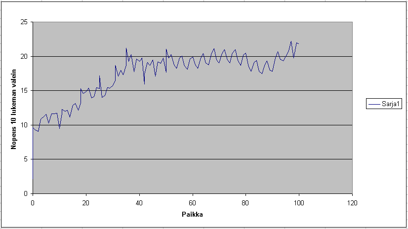
There is some jumping up and down in the above graphs and it’s not yet clear if that comes from the measurement process, the way the values are calculated or if the construction of the hydraulic motors itself causes this kind pulsating rotation.
Last we have position as a function of time:
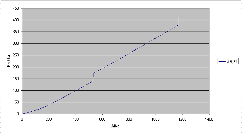
Here the couple big jumps are glitches in the logging process which was fixed and should be gone in the data logged next time.
For measuring the tree diameter there is a quadrature encoder connected to the track so that the encoder follows the amount of track opening and as a result gives a value relative to the diameter of the tree that is between the tracks. The encoder reading isn’t linear to the track opening so some calibration is needed.
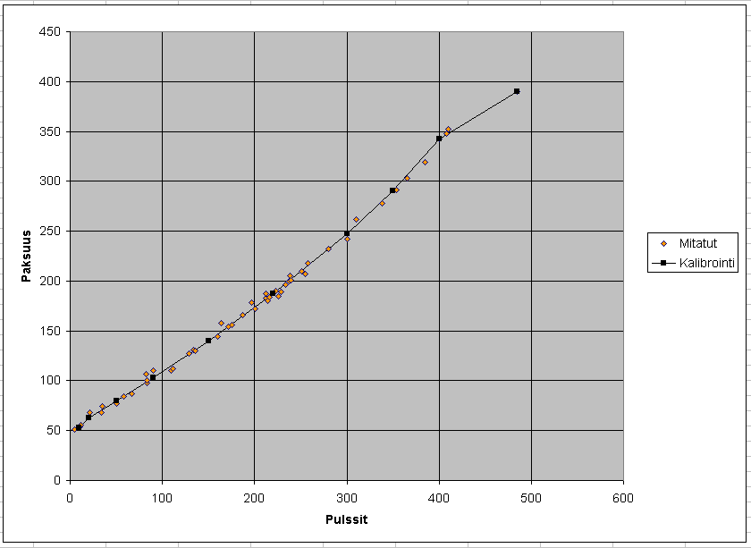
To get an idea of the relation between the encoder pulse values and the actual diameter some logs were measured and the readings written down.
Here are the results. The line on top of the measured points is the result of a 10 point look up table fitted over the points. The relation between the pulse reading and actual diameter was more linear than I expected. Certain parts of the curve need some additional data points to verify the behaviour.
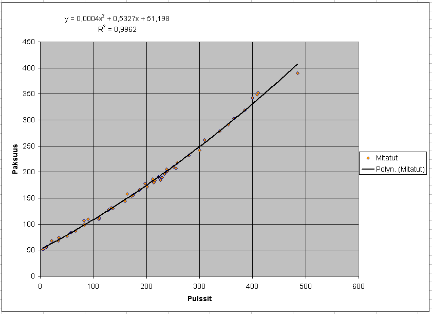
Here is a second degree polynom fitted to the points to see how accurate results could be had this way.
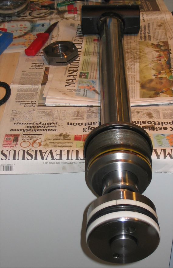
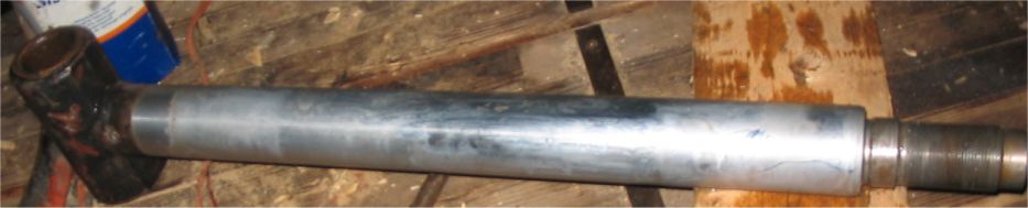
One cylinder rod in the crane was in quite bad shape with dents and scratches all over. So it was replaced with a new one and also all the seals replaced in the process.
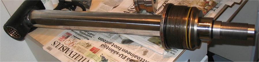
Old rod, not very good photo though…
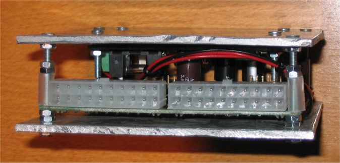
Originally I was planning all kinds boxes to put the head unit board into. But then I thought that as in the head there is a sealed aluminium box into which all the solenoid and sensor cables are wired to it might not be necessary to have another closed box for the circuit board after all. At least for this board version. So I decided to just cut some pieces of aluminium sheet and sandwich the boards between them to provide some physical protection for the assembly.
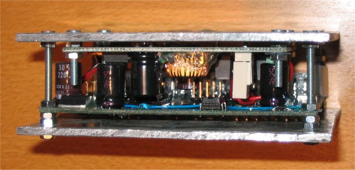
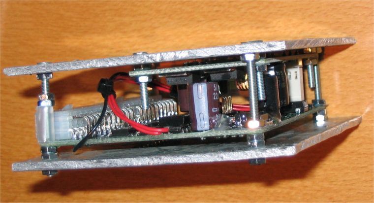
There is two boards now, the other being a step down switching power supply. The reason for this is that I wasn’t really comfortable with the temperatures of the 5 V linear regulator on the head unit board with the 24 V supply voltage. The original design was planned for 12 V supply voltage. Next version should have the switching regulator on board.
The head module supports updating the software through the CAN bus so that after it has been installed in it’s box and buried under the protective covers it’s not necessary to get physical access to it anymore unless some hardware modifications are needed or signals need to be measured with external equipment. The main module has the support for performing this software update for the head module from a memory card so carrying a laptop with you isn’t necessary if all you need to do is loading new software version. Also the main module can load new software from a memory card to update itself.
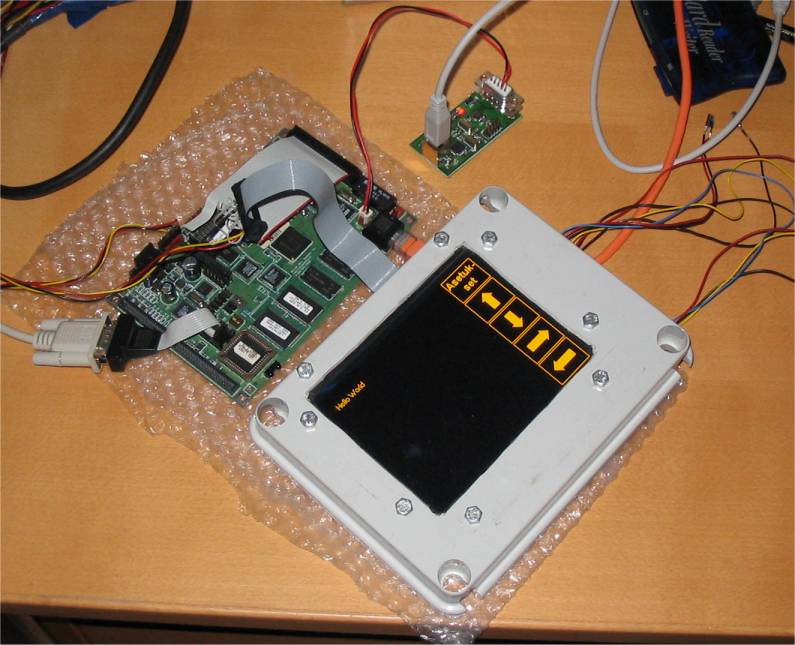
And finally the head module mounted in it’s box:
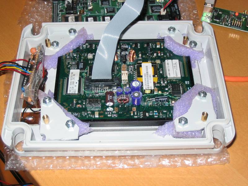
Here we have the head module board sprayed with some protective plastic coating hopefully making it a bit more resistant to the environment it is going into. Also the larger electrolytic capacitors will be glued to the board.
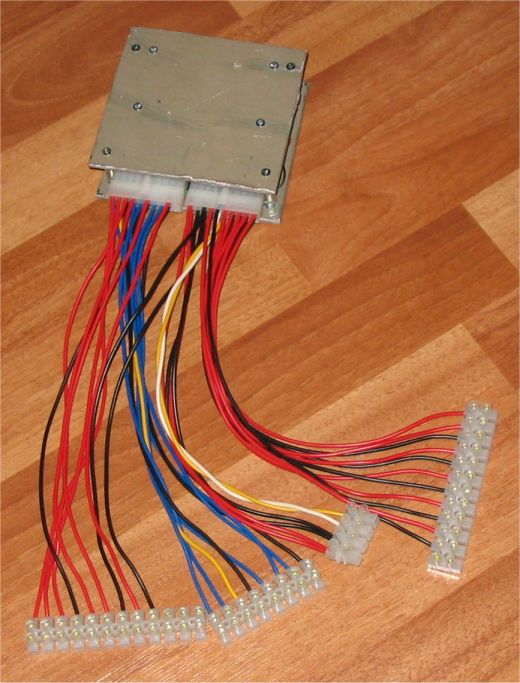
Here’s also some wiring built to go between the head unit connectors and the valve solenoid and sensor cables in the head.
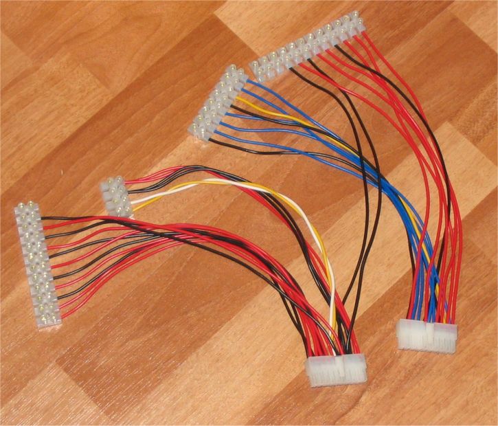
There will also be another DC/DC stepup converter in the system as the valves in the harvester head also have 24V solenoids. Even if this requires another 12V to 24V stepup converter it might not be that bad thing as the current going to the head will be smaller than it would be with 12V solenoids so the requirements for the cable carrying power for all the valves to the head from the base machine are less.
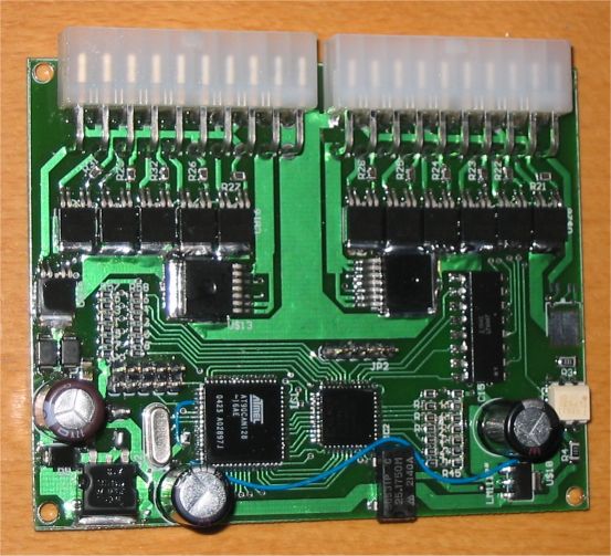
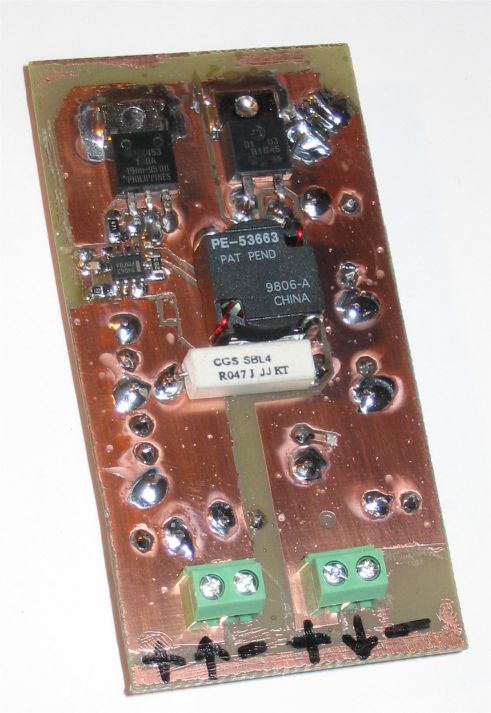
You can see that the result of the etching isn’t that good. This reminded me that after not using the developer and etching liquids for over a year it’s a good idea to make new liquids instead of just using the old. But even if there were some difficulties the result seems to be working. The inductor used for the converter feeding the harvester head is different one than in the photo though.
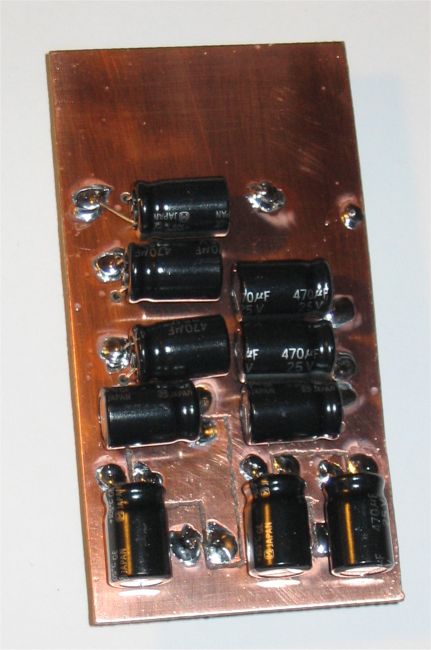
Electrolytic capacitors were moved to the backside to make it easier to solder them on the board.
A new DC/DC converter using a modern two phase controller IC is also under work. But looks like it’s not needed for this application yet as the above converter seems to be handling the current requirements of the harvester head just fine. And the parts for this converter were found from existing supplies which is not something that can be said about a converter using a modern controller IC, very low RDSon FETs and high performance inductors.
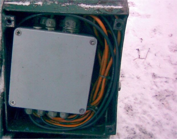
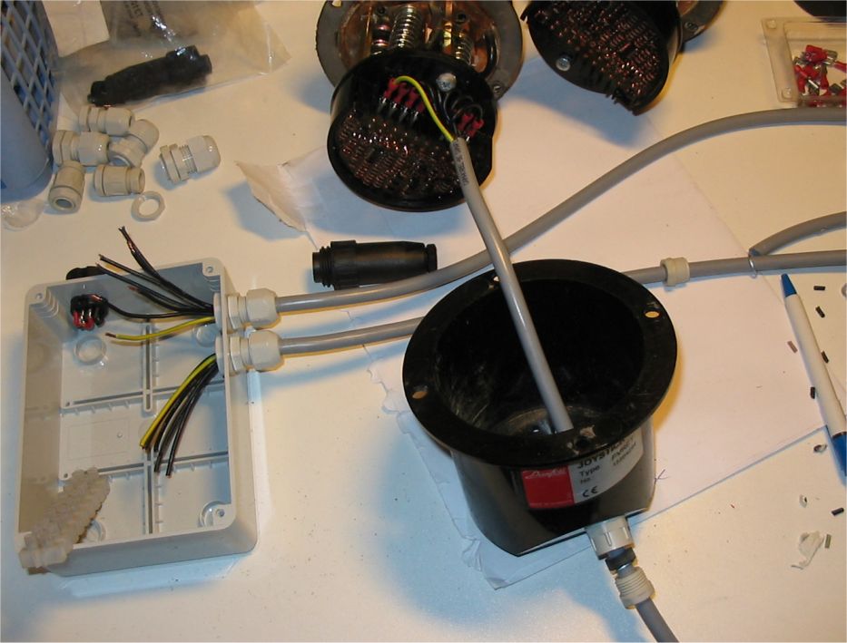
In this picture we have wires from the joysticks connected to the connectors going to the valves. For now there is a straight connection between the joysticks and the valves and nothing in between. Later there could be some more electronics coming into the box that would filter the signal coming from the joysticks before forwarding it to the valves. Maybe add a microcontroller with A/D converter for reading the joystick signal and D/A converter for outputting the valve control signal. And with the microcontroller there in between some software controlled filtering could be done. Maybe also could connect the joysticks to the harvester head control system using a CAN bus. There can be seen two black connectors for the outgoing signals. Only one is used for this 4 section PVG32 valve and the other is there so that these same joysticks can be also used with another crane with a 6 section PVG32 valve.
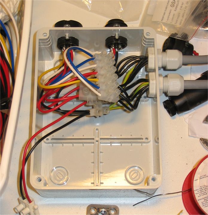
The box looks half empty in this picture but there will also be a 12V to 24V DC/DC converter board in the box as the valve has 24V electronics and the tractor has 12V electric system. Having regulated 24V voltage for the valves and joysticks might also give some additional benefits as the voltage used for the valve position control signal doesn’t change with the vehicle voltage.
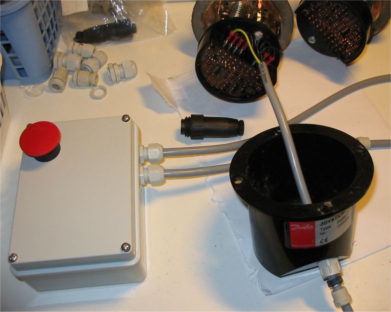
Also in the picture below the valve cables have been connected to the connector in the box end.
Beginning the wiring job for the joysticks.
The box also has an emergency stop.
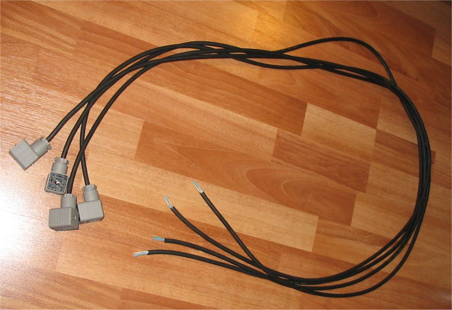
Cables built for connecting the box to the valves.
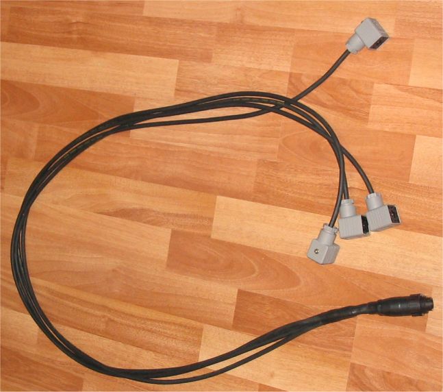
Here’s the joysticks for the PVG32 valve.
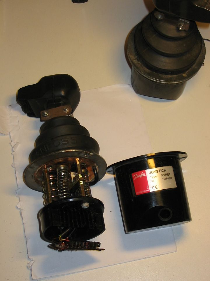
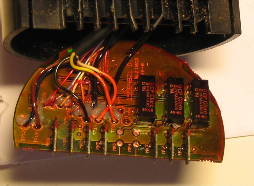
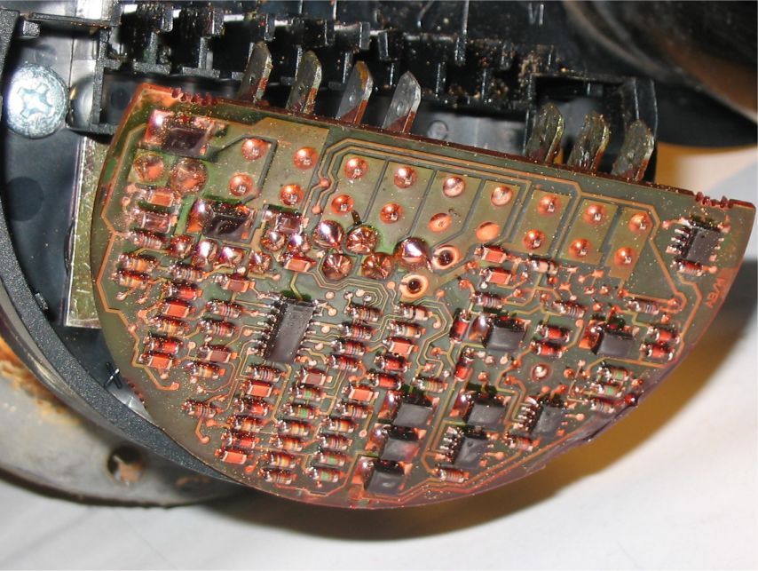
Circuit board found inside the joystick:
It has been quiet for several months now and not much has happened during that time. But now it’s time to get some projects moving forward again.
Here’s couple new pictures. These were mostly done during the summer already.
First we have the head module board mostly assembled now. Also some new fixes and additions have been included.
Here’s also the Planar display attached into the lid of the box that will contain the main hardware. This particular display unit doesn’t have the mounting tabs so some other way to mount it had to be figured out. To not spend too much time in this phase some holes were just drilled through the lid and everything bolted together. Later there will hopefully be some arrangement that will make the whole thing look cleaner and not have the mounting hardware visible to the outside. In front of the display panel there is a 4 mm thick acrylic sheet for protection that can be replaced if it gets too many scratches. Well there already is quite many visible scratches but they don’t seem to really affect the visibility of the EL display.
In the next photo from the backside we can see 5 rectangular pieces cut from a copper circuit board glued behind the plastic in the left side. Also there is the small board with the DIP package IC and some other components and different color wires coming out of it. These are capacitive sensing buttons made with a QProx touch sensing chip. Originally this was just a test of how well the sensing works but at least for now it has worked well enough that they have stayed there. This also needs a new board that integrates the 5 sensing elements and the QProx circuitry on one PCB instead of the current temporary solution.
Using a touchscreen was also considered as it could have made it possible to make a more intuitive user interface. But after considering the environment where this is used and that the touchscreen would add another layer between the display and viewer’s eyes the decision was made to use just the capacitive touch sensing buttons. Also this interface is mostly just used for changing settings which shouldn’t happen that often.
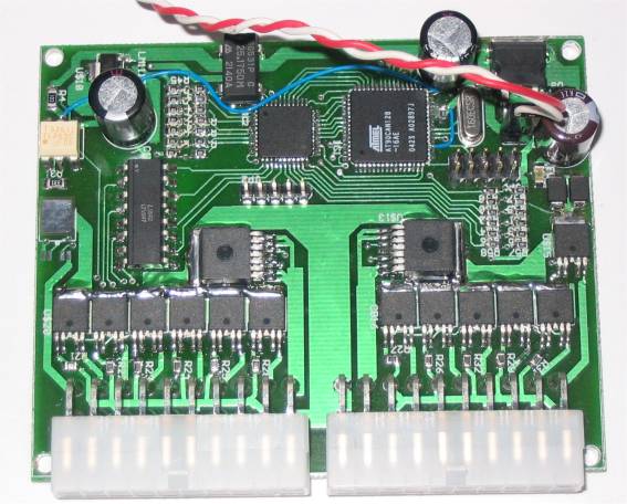
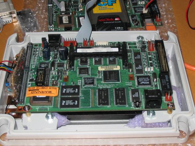
In the next photo the processor board is mounted behind the display.
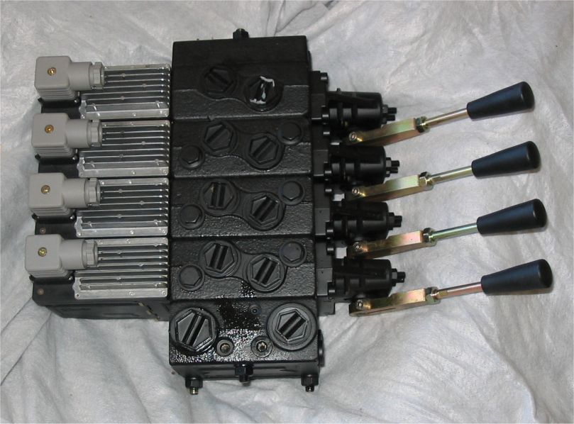
Last photo for this update is a Danfoss PVG32 proportional valve which will be used to control the crane. One more thing that needs to be done is the electrical wiring between the joysticks and this valve.