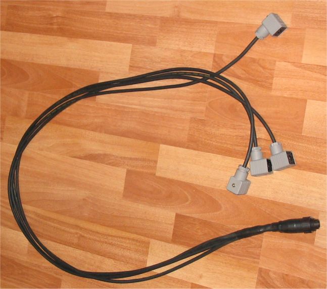
In this picture we have wires from the joysticks connected to the connectors going to the valves. For now there is a straight connection between the joysticks and the valves and nothing in between. Later there could be some more electronics coming into the box that would filter the signal coming from the joysticks before forwarding it to the valves. Maybe add a microcontroller with A/D converter for reading the joystick signal and D/A converter for outputting the valve control signal. And with the microcontroller there in between some software controlled filtering could be done. Maybe also could connect the joysticks to the harvester head control system using a CAN bus. There can be seen two black connectors for the outgoing signals. Only one is used for this 4 section PVG32 valve and the other is there so that these same joysticks can be also used with another crane with a 6 section PVG32 valve.
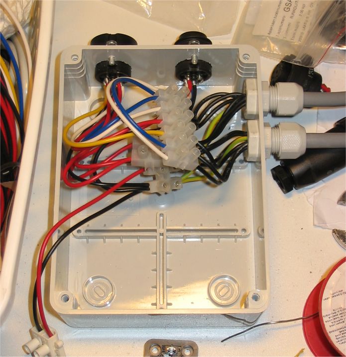
The box looks half empty in this picture but there will also be a 12V to 24V DC/DC converter board in the box as the valve has 24V electronics and the tractor has 12V electric system. Having regulated 24V voltage for the valves and joysticks might also give some additional benefits as the voltage used for the valve position control signal doesn’t change with the vehicle voltage.
Also in the picture below the valve cables have been connected to the connector in the box end.